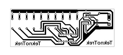
LED Chaser Circuit using 555 Timer IC & CD4017: A Comprehensive Guide
In the realm of electronics, creating captivating light displays is a common endeavor for hobbyists and enthusiasts alike. Among the various techniques employed to achieve this, the "LED chaser" circuit stands out as a popular and visually appealing project. This circuit utilizes a combination of electronic components, including the 555 timer IC and the CD4017 decade counter IC, to generate a mesmerizing sequence of illuminated LEDs.
Understanding the Core Components
1. 555 Timer IC: The 555 timer IC is a versatile integrated circuit widely used for generating various timing signals. It features two stable states and an externally triggered mode, making it suitable for creating oscillating or pulse-based circuits.
2. CD4017 Decade Counter IC: The CD4017 decade counter IC is a sequential logic circuit capable of counting from 0 to 9. It receives clock pulses from an external source and advances its internal count with each pulse.
Circuit Operation
1. Power Supply: The circuit is powered by a DC power supply, typically ranging from 5V to 12V. This power is distributed to the various components, providing the necessary energy for their operation.
2. 555 Timer Configuration: The 555 timer IC is configured as an astable multivibrator, generating a continuous square wave signal. The frequency of this signal is determined by the values of resistor R1 and capacitor C1.
3. CD4017 Clock Input: The square wave output from the 555 timer IC is connected to the clock input (pin 14) of the CD4017 decade counter IC. This clock signal drives the internal counting sequence of the CD4017.
4. LED Connections: Each output pin (Q0 to Q9) of the CD4017 decade counter IC is connected to a corresponding LED through a current-limiting resistor. As the internal count of the CD4017 advances, each LED turns on sequentially, creating the chasing effect.
Circuit Design Considerations
1. Component Selection: The choice of resistors and capacitors depends on the desired frequency of the LED chasing sequence and the current requirements of the LEDs.
2. Power Supply Capacity: The power supply should be able to provide sufficient current for all the LEDs and the ICs.
3. Breadboard or PCB: The circuit can be prototyped on a breadboard for testing and debugging, and later transferred to a printed circuit board (PCB) for a more permanent setup.
Conclusion
The LED chaser circuit using the 555 timer IC and CD4017 decade counter IC offers a simple yet effective approach to creating eye-catching light displays. By understanding the operation of these components and carefully selecting circuit parameters, hobbyists can successfully construct and enjoy this captivating electronic project.
 Reviewed by TeknoTrek
on
May 03, 2024
Rating:


